
Signal Routing Port Using Shift Registers on PIC18Q71 Series MCUs
This article describes the new Signal Routing Port (the SRPORT) peripheral integrated into the PIC18-Q71 series of microcontrollers (MCUs) and future devices. We will discuss how The SRPORT can be used in conjunction with other peripherals to implement Serial Input Parallel Output (SIPO) shift registers.
Understanding the Problem
In MCUs with limited I/O pins, pin availability is often a major system limitation. Often, there is a trade-off between the number of pins available and the cost, size, and complexity of the chip itself, making it difficult to find the perfect balance. Applications involving the interconnection of multiple peripherals often run into the problem that not all peripheral signals can be directly interconnected to each other, and the signals need to be routed through external I/O pins to establish the connection. This can be undesirable as it limits the ability of the MCU to connect to multiple external components when needed, reducing the overall functionality of the system.
There are solutions to this situation, such as using a device with a higher pin count to ensure that all connections can be established, or adding additional hardware (such as an I/O expander) to increase the number of pins available. While these solutions may seem feasible, it is important to understand the tradeoffs as they may increase the complexity of the system and therefore the overall cost.
What is a Signal Routing Port?
The SRPORT is a software interface that mimics a physical hardware port on a microcontroller, essentially acting like a regular I/O port that is not physically connected to an external pin. This allows communication with a device as if it were connected to a physical port on the microcontroller, eliminating the need for any additional physical I/O lines in the application. The SRPORT brings advanced interconnectivity to the design, ultimately minimizing the need for external pin wiring. This allows users to create customized configurations without complex software development or extensive PCB modifications.
The SRPORT module is a versatile hardware solution consisting of eight virtual input and eight virtual output pins. These pins are flexible enough to meet specific application requirements. Each signal routing pin provides a range of input options, including the outputs of various core-independent peripherals, which allows hardware-based solutions to exchange data between selected peripherals and virtual pins.
For applications requiring advanced synchronization and timing, the SRPORT offers a wide selection of clock sources, including those from peripherals. Each signal routing pin is equipped with triggers to help synchronize signals when needed, ultimately contributing to the design of hardware-based state machines.
The SRPORT is used as an advanced input selection multiplexer to connect digital peripheral outputs to the inputs of other peripherals internally via Peripheral Pin Selection (PPS), eliminating the need to route these signals to external I/O pins for communication between peripherals. The range of input selection also includes the output of the next signal routing pin immediately adjacent to the input as an input. This, in conjunction with the flip-flops provided on each signal routing pin, allows shift register operation. Finally, the SRPORT provides dedicated level change interrupts. This is useful when used in conjunction with trigger events from other peripherals such as DMA controllers or analog-to-digital converters.
Creating Serial Input Parallel Output (SIPO) Shift Registers with The SRPORT
Now that we have a good understanding of the SRPORT, we will now discuss how our application team implemented a SIPO shift register using SRPORT and other peripherals.
This application uses a Curiosity High Pin Count (HPC) board with a PIC18F46Q71 microcontroller.
The following shows a high-level block diagram of how the code example works.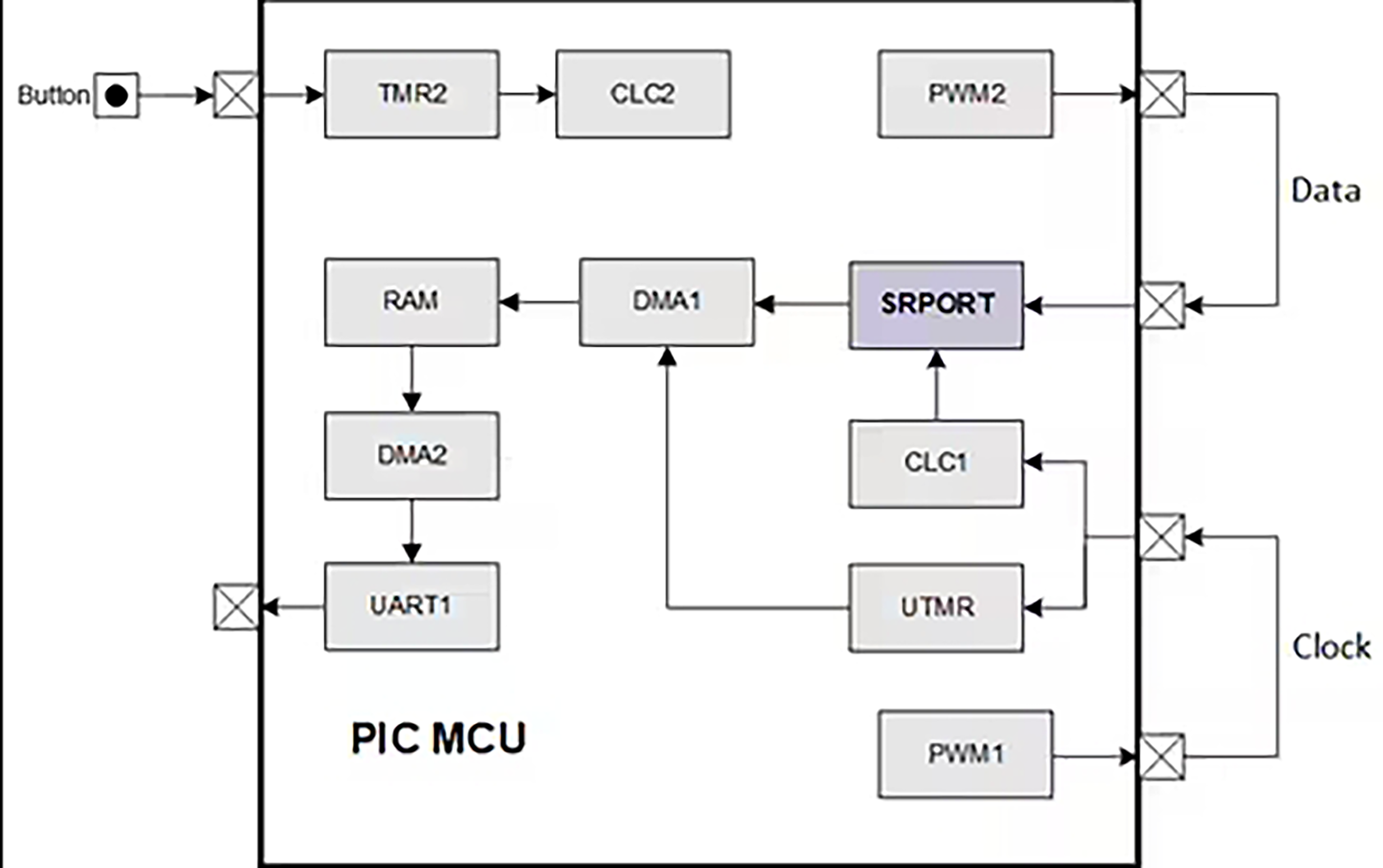
What is a Serial-In-Parallel-Out (SIPO) Shift Register?
A shift register is a digital circuit that stores and transfers binary data. A shift register consists of multiple flip-flops cascaded to each other, where each flip-flop can store one bit of data and the entire chain can store multiple bits of data.
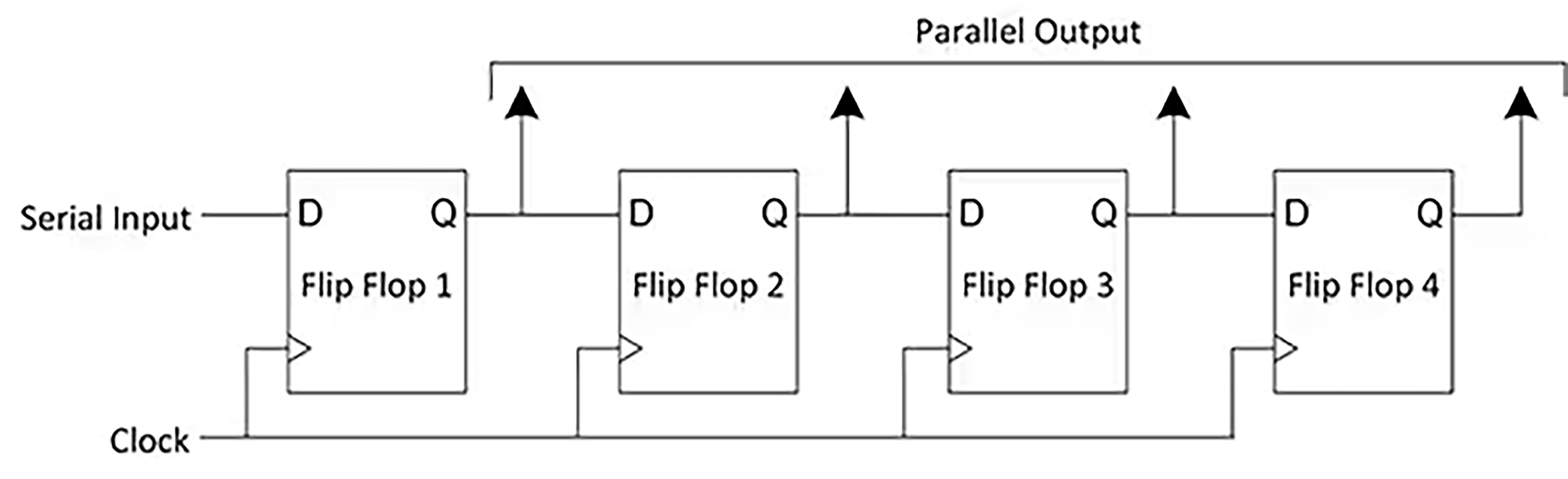
A SIPO shift register is a digital circuit that can store and transfer data in a series of flip-flops. It receives data one bit or byte at a time via a serial input and outputs the entire set of bits or bytes in parallel. A SIPO shift register usually consists of multiple flip-flops interconnected with each other, using their data and clock signals as inputs.
The basic representation of a SIPO shift register is shown below.
Principle of Operation
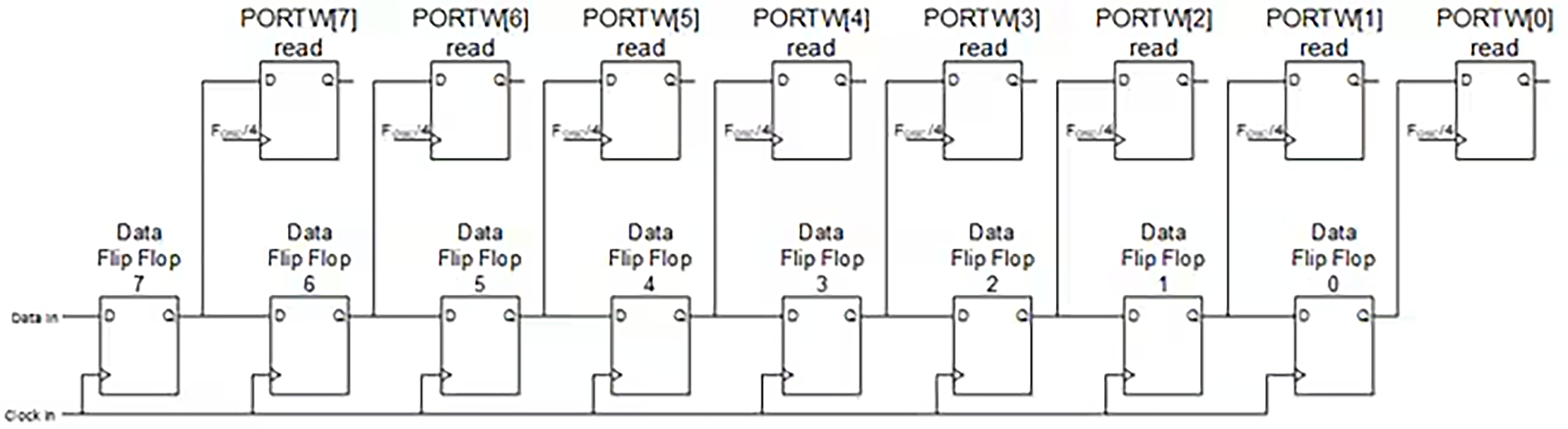
The SRPORT module is responsible for storing and shifting data based on incoming clock signals. To configure the SRPORT as a shift register, the SRPORT allows one of its input selection options to take the output of the immediately next signal routing pin as an input.
A graphical representation of this is shown below.
The SRPORT takes clock signals and data from the pulse width modulator (PWM) peripheral. The PWM1 module generates a 1 kHz clock signal that is used as the clock input to the SRPORT. To utilize this signal as the clock signal for The SRPORT, the Configurable Logic Cell (CLC) is used to redirect the clock signal to the clock input selection of the SRPORT.
The PWM2 module is used to generate a data signal as an input to the shift register. The data generated by PWM2 is shifted and stored on each rising edge of the 1 kHz clock signal. Once eight clock cycles have occurred, an 8-bit value representing the data from the first eight clock cycles is stored in the PORTW register. Once the eighth clock cycle occurs, the Universal Timer (UTMR) triggers a Direct Memory Access (DMA) transfer to move the data from the SRPORT to RAM. Subsequently, another DMA module is used to move the data from RAM to the UART's transmit buffer for visualization on the data terminal.
Finally, an on-board pushbutton on the Curiosity HPC development board is used to initiate each round of data transfer. In order to address possible anti-jitter issues with the pushbuttons, the Timer2 module was used in conjunction with the CLC module to create a hardware-based, no-code, anti-jitter solution for the pushbuttons.
In summary, this demonstrates how shift registers can be implemented efficiently using the SRPORT as well as other core-independent peripherals.
If you're interested in this article, you can click through to see our other articles.