
How Should a Position Sensing System with an AMR Angle Sensor be Designed
As governments push to reduce greenhouse gas emissions from internal combustion engine (ICE) vehicles, original equipment manufacturers (OEMs) are redesigning mechanical systems into electronic control systems. High levels of system connectivity and smart technologies are making self-driving cars a reality, resulting in a growing demand for electronicsand software algorithms to meet safety requirements, including International Organization for Standardization (ISO) 26262.
Sensors, especially angle sensors, are essential in systems that need to meet functional safety standards. It helps monitor and provide torque and angle information that is required to efficiently drive or operate various automotive systems.
Designing an EPS System
An electric power steering (EPS) system consists of a steering column, an electronically controlled steering motor, and an electronic sensing and control mechanism. As the driver turns the steering wheel, the motor (usually a brushless DC motor) assists in steering, which replaces traditional mechanical and hydraulic systems.
The benefits of EPS systems include faster and smarter operation, reduced CO2 emissions, improved fuel efficiency and an enhanced user experience. The driver provides system inputs at the steering wheel interface. Sensors detect the position of the motor shaft and steering wheel rotation and send the data to the electronic control unit (ECU). Figure 1 highlights the basic elements of the EPS system.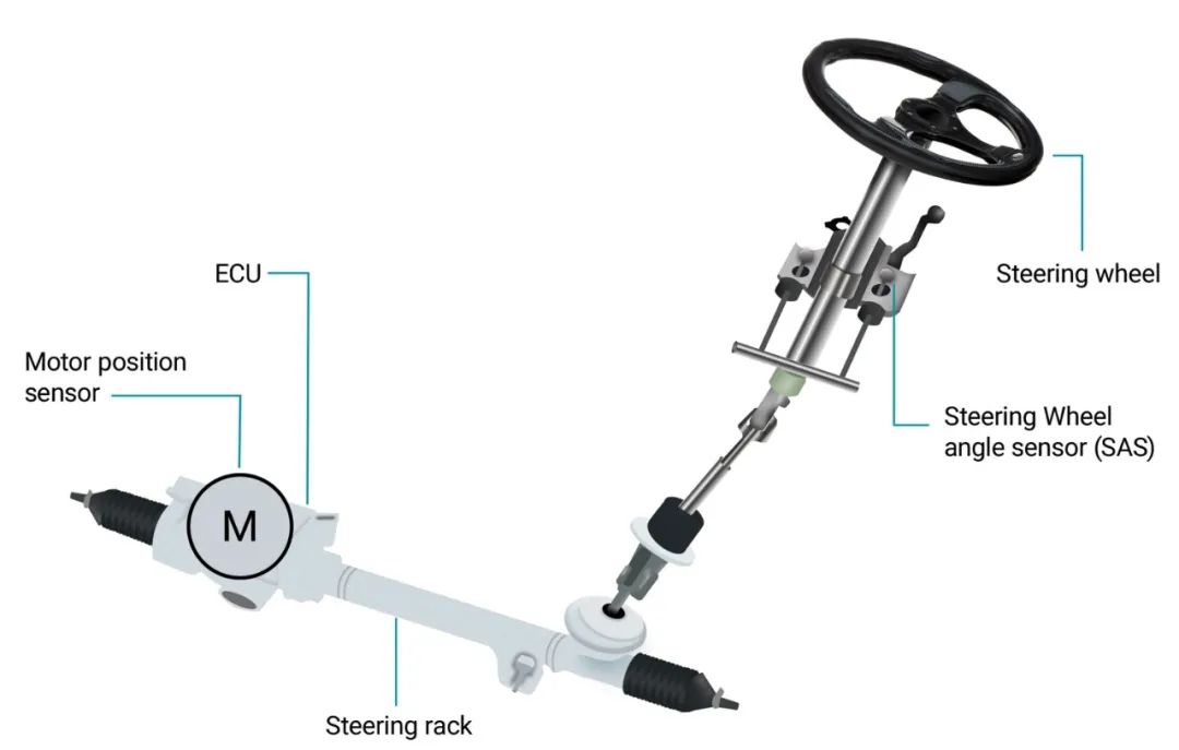
Figure 1:EPS system
The components required to design an EPS system include microcontrollers, sensors, power supplies, motor drivers, and transistors. These components are critical to the efficient communication and operation of the system. As shown in Figure 2, the controller LAN is the bus standard used to connect the ECUs in a vehicle.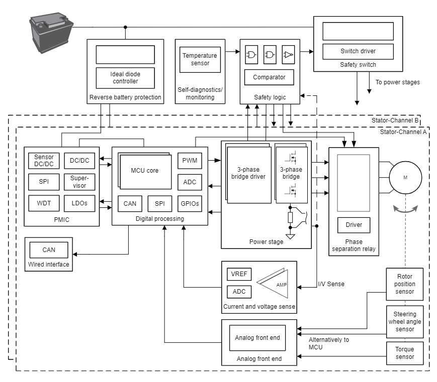
Figure 2: Block Diagram of EPS System
The TMAG6181-Q1 is an anisotropic magnetoresistive (AMR) angle sensor. It has an integrated signal conditioning amplifier that provides differential sine and cosine analog outputs related to the direction of the applied planar magnetic field.
With a latency of less than 2µs and an angular error of only 0.4 degrees, the TMAG6181-Q1 contributes significantly to system performance and efficiency. The sensor's integrated turns counter tracks the motor's speed up to 32,000 revolutions per minute (rpm) in normal operation mode and up to 8,000 rpm in low-power mode. It also supports a variety of device- and system-level diagnostic functions to detect, monitor, and report faults during device operation. For example, in sleep or fault mode, the TMAG6181-Q1 AMR sensor outputs will enter a high impedance state. The use of a pull-down or pull-up resistor ensures that the microcontroller can detect faults.
An external microcontroller is usually required to process the AMR output signal and extract the angular position of the EPS motor or steering wheel. The AMR angle sensor in the TMAG6181-Q1 can be used in either single-ended or differential output modes; the latter mode eliminates common-mode interference from the system. The differential output sine and cosine signals from the AMR sensor are proportional to the angle of the applied magnetic field, and the output voltage of the AMR sensor is proportional to the supply voltage to ensure that the external ADC can reference the supply voltage.
Figure 3 illustrates a typical application diagram where the differential output signals SIN_P, SIN_N, COS_P, and COS_N are connected to four single-ended analog-to-digital converters in an external microcontroller that communicates with the ECU in the EPS system.
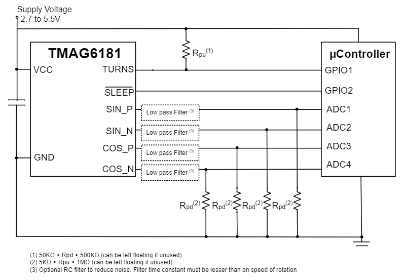
Figure 3: TMAG6181-Q1 in Single-Ended Output Mode
The use of a differential ADC, if available, is recommended as it improves reliability. For high accuracy, the load capacitors and resistors must be matched to each other. the TMAG6181-Q1 can drive capacitive loads up to 10nF directly on the AMR output pins and resistive loads with pull and sink currents up to 1mA. This enables smooth and reliable operation of the EPS system.
To simplify compliance, ISO 26262 system design documentation is available for the TMAG6181-Q1, with automotive safety integrity levels up to Level B.
Designing E-Bike and E-Scooter Systems
An e-bike is a bicycle that contains five key components: motor, battery, controls, sensors, and display. The motor is an integral part of the e-bike and can be used to provide the extra power needed during pedaling. To efficiently and reliably rotate the motor (which can be mounted front, center, or rear), an angle sensor is required, as shown in the block diagram in Figure 4.
An electric scooter is a scooter that converts from a gas drive to electric. Its motor drive system design is very similar to that of an electric bicycle, except that it is not as complex. An electric scooter design only needs to supply power to the motor when the gas pedal is depressed, but an e-bike design must also monitor the rider's pedal power to determine the amount of power supplied to the motor. Different regions require e-bikes and e-scooters to meet similar levels of safety as the automotive industry.
Figure 4 highlights the components required to develop an e-bike system. Angle sensors provide angular feedback, which is then calculated by the microcontroller to efficiently and reliably rotate the motor. AMR sensors are typically limited to 180 degrees, but the TMAG6181-Q1 adds two independent Hall-effect sensor outputs in the X and Y axes, which extends the sensor's angular range to 360 degrees.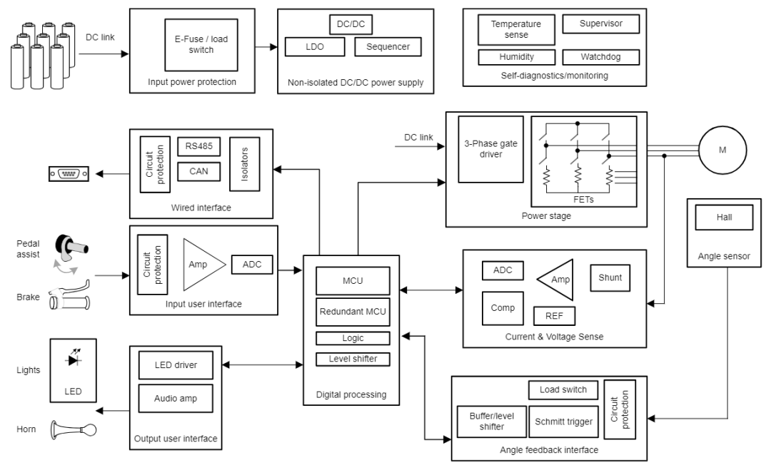
Figure 4: E-Bike Block Diagram
Conclusion
Today's cars and e-bikes contain multiple ECUs to drive and control advanced functions. Designing an EPS system, e-bike or e-scooter requires precise control from the ECU for efficient and reliable operation. the TMAG6181-Q1 enables faster and more precise motor control, helping to improve system performance.
If you're interested in this article, you can click through to see our other articles.